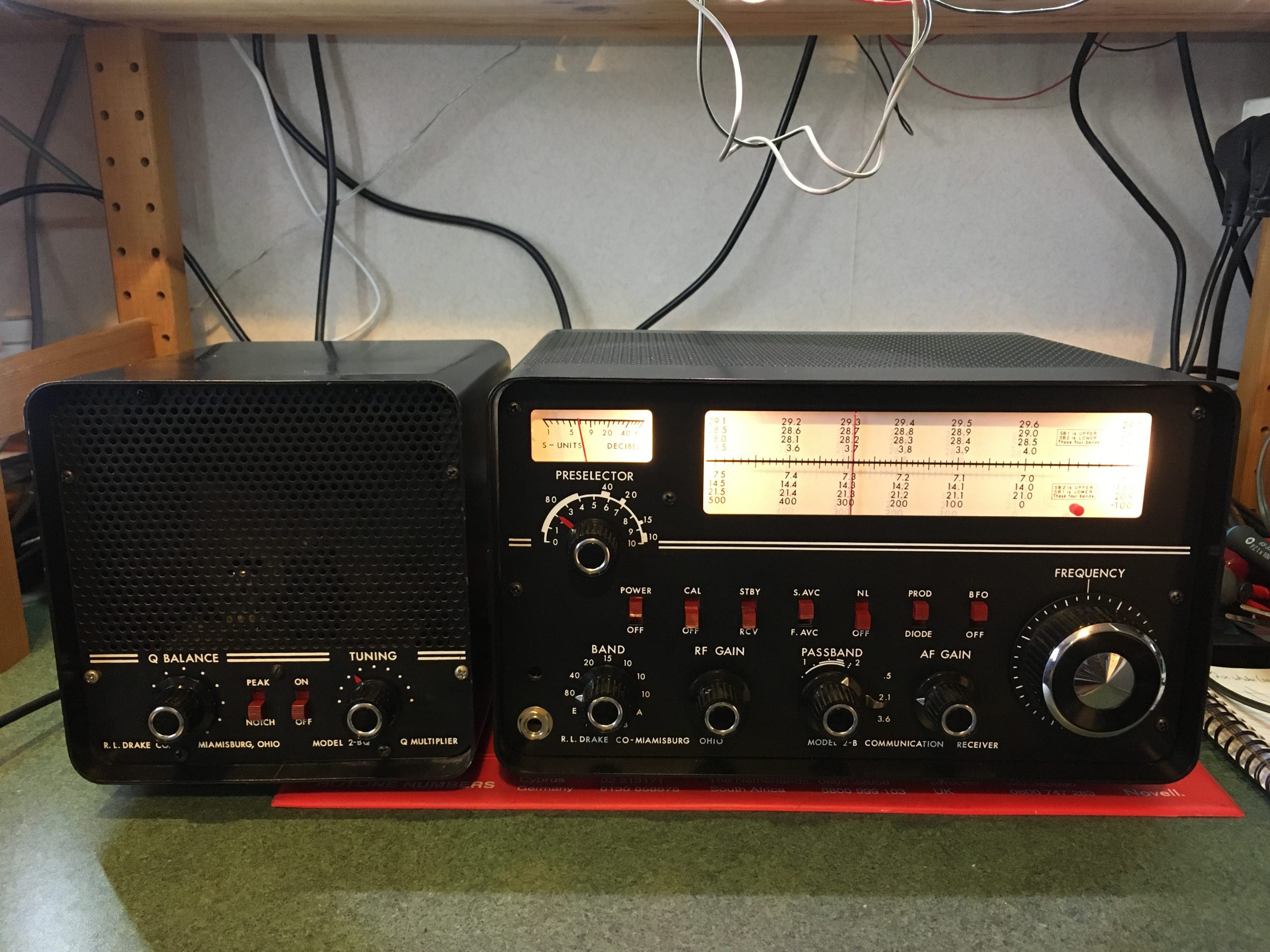
Drake 2B and 2B-Q
This is my second Drake 2B, the first one was a bit scruffy but worked well…this one is in fantastic condition and also worked well. That was until it had a break for a few months. When I powered it up towards the end of last year, there was a ‘tick’ sound followed by hum, yet the receiver did continue to work. The HT smoothing capacitor(s) had failed when I checked.
The Drake 2B is a truly amazing little radio. It originated in 1961 when many manufacturers were still offering heavy ‘boatanchor’ style receivers and transmitters. In 1959, Drake released the 1A and soon after, the 2A. These radios were simple to use, compact and very light weight compared to the receivers of the time. The 2B followed the 2A and its performance is really quite superb; if you get the chance to buy one, I recommend that you do.
eHam describes the radio thus ‘The DRAKE 2-B is an extremely versatile communication receiver designed to bring you top performance in reception of all modes of amateur transmission in a compact package. It is a triple conversion superheterodyne receiver employing crystal controlled high frequency oscillators, a highly stable variable oscillator tuning the same range on all bands, and for selectivity a steep-sided L-C filter at the 50 Kc I.F.‘ and gives it 4.9 out of 5 stars.
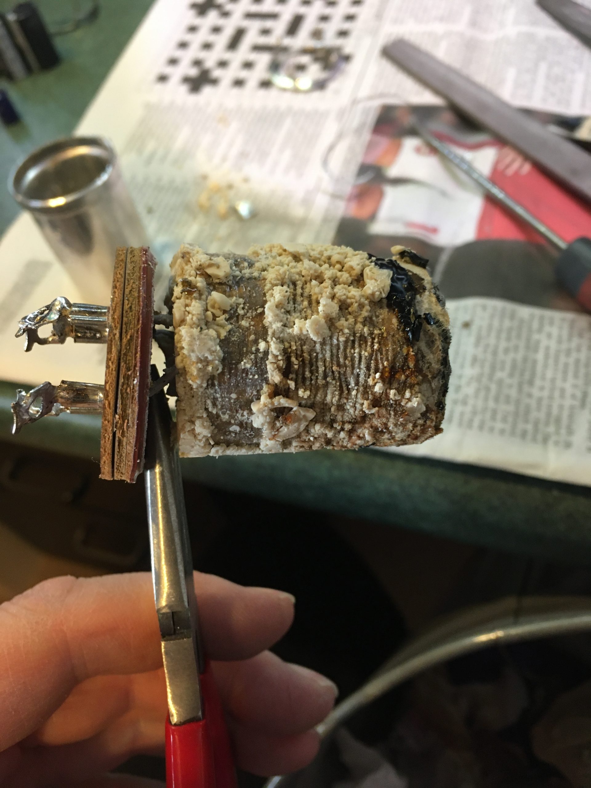
C70 unwrapped
As mentioned previously, it’s a triple conversion valved amateur band receiver, using a 50KHz final IF and really smooth LC filtering. Another great feature is passband tuning, so you can shift the selectivity window across the ‘passband’ of a received signal. The 2B is one of my all time favourite receivers, and I use it with the optional 2B-Q speaker and Q multiplier; my radio has a crystal calibrator module fitted too.
Gerry O’Hara, a prolific Eddystone enthusiast, wrote an article on the Drake 2B he had for repair, which you can access that here, so there seems little point in me duplicating his excellent work.
My receiver needed the dual 100uF can type electrolytic (C70a and C70b on the circuit diagram) restuffing with modern capacitors, and I replaced the audio output cathode decoupling capacitor (C78 on the circuit diagram) too. On checking the rest of the radio, I found the alignment and functionality good, so no further work was needed.
The end of the main smoothing capacitor innards are held in by crimping the can over the paxolin disc, carrying the connector. Inside you will find the old capacitor plus some black pitch-type substance. I’m sure you can leave the pitch inside, but I cleaned mine out using heat outdoors; it smells bad so don’t do it indoors.
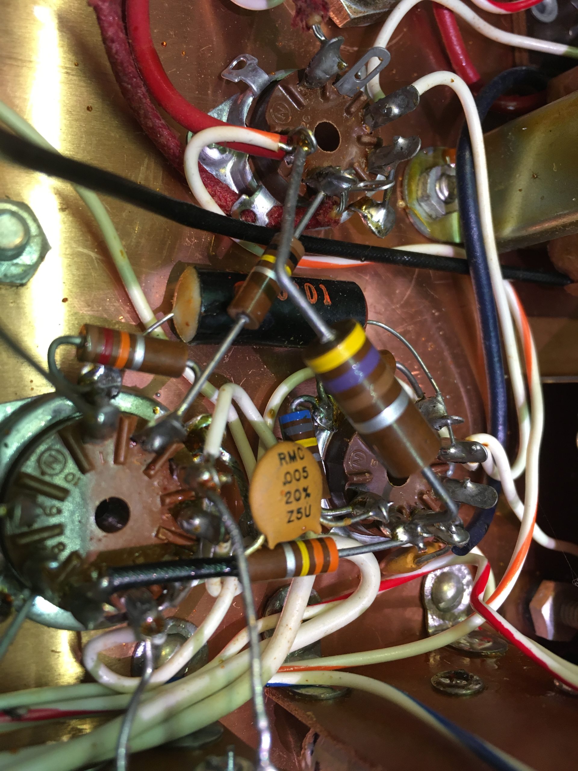
C78 cathode decoupling
The new capacitors were soldered to the tag stumps on the inside of the paxolin end disc, then refitted in the can. The can has a lip which I ran a line of EvoStik around, before pressing in the disc and crimping over the lip of the can as far as possible. I can’t find the photo I took of the new capacitors soldered to the end cap, but I’m sure you can work it out.
Replacing the cathode decoupling capacitor was relatively straighforward; it’s black with beige ends and it’s shown here hiding under a large 470 ohm resistor.