The Yaesu FT-840 was, and still is, a very popular ‘shack in a box’ HF radio.
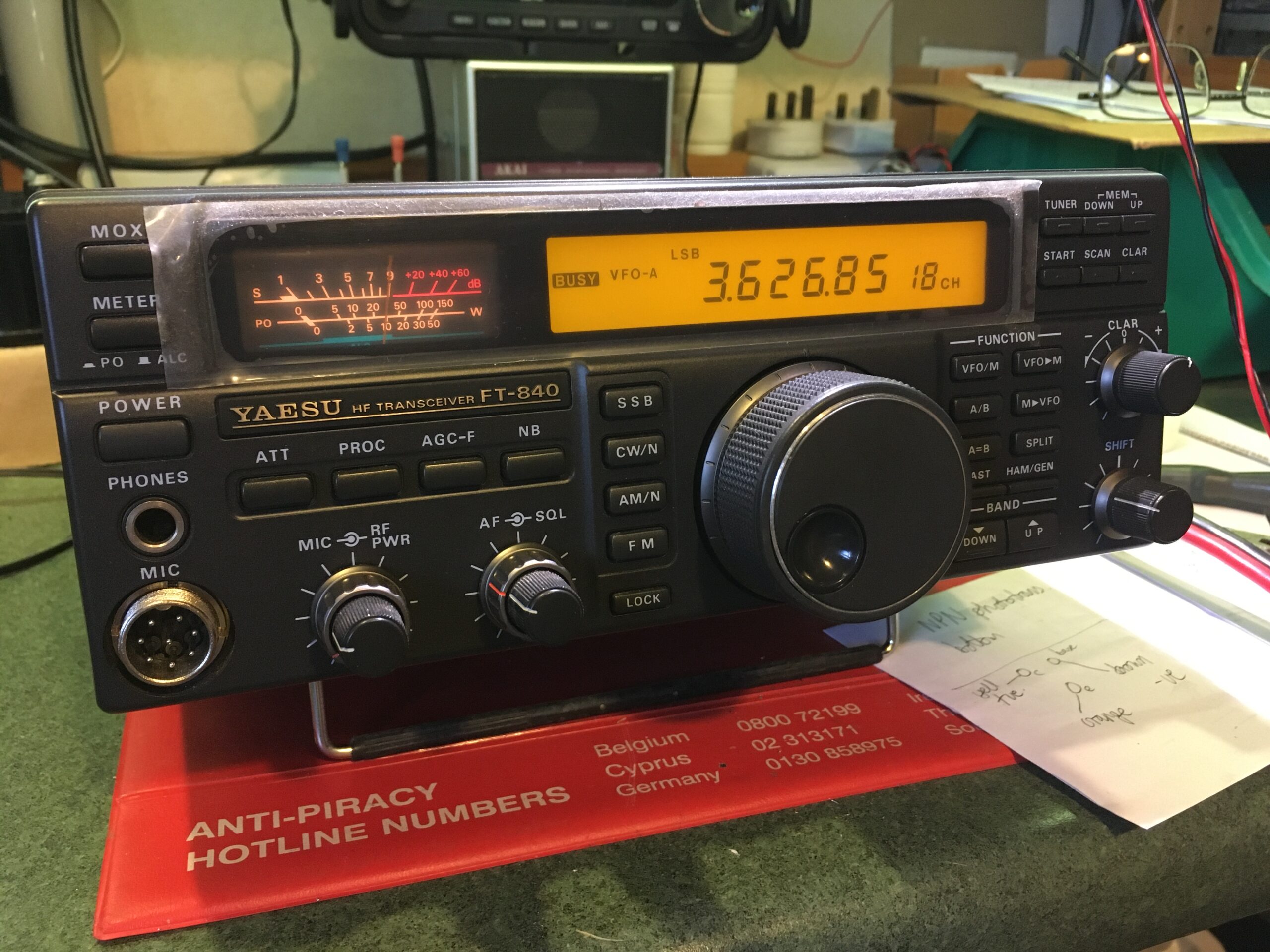
My Yaesu FT-840
The basic specification is: ‘The Yaesu FT-840 is a compact transceiver with up to 100 Watts output power on all HF amateur radio bands in CW, SSB and FM modes, and up to 25 Watts in AM. Dual/triple conversion 100 kHz to 30 MHz receiver with IF-shift, reverse CW, noise blanker, attenuator, dual VFOs. 100 memories, flexible scanning features, TX speech processor, two DDS synthesizers, tuning knob torque adjustment. Manufactured in Japan, year of introduction 1993.’
They do get their odd problems but are a great radio, especially when partnered with the MH-1 microphone.
I bought mine with a known fault…the encoder appeared to be faulty. When turning the tuning knob, the last digit on the display flickered up and down one step; a sure sign that one phase of the encoder isn’t working. The radio was mint otherwise…how hard can it be?
If you encounter a similar problem, this might help you out. The first thing to do is download a copy of the service manual; a copy is available from several places, so Google is your friend here. You might not need it, but ‘just in case’.
First, unplug the power, mic, aerial and anything else connected to the radio.
Remove the rubber ring from the VFO knob and use an Allen Key to remove the knob itself. Next, remove the variable friction spring and plastic bush from the encoder spindle. Now, remove the bottom and top covers from the radio, taking care to carefully disconnect the speaker. Remove the two top screws holding the sides of the front panel and slacken the bottom two so that it can hinge down.
HINT: take pictures of what you are doing.
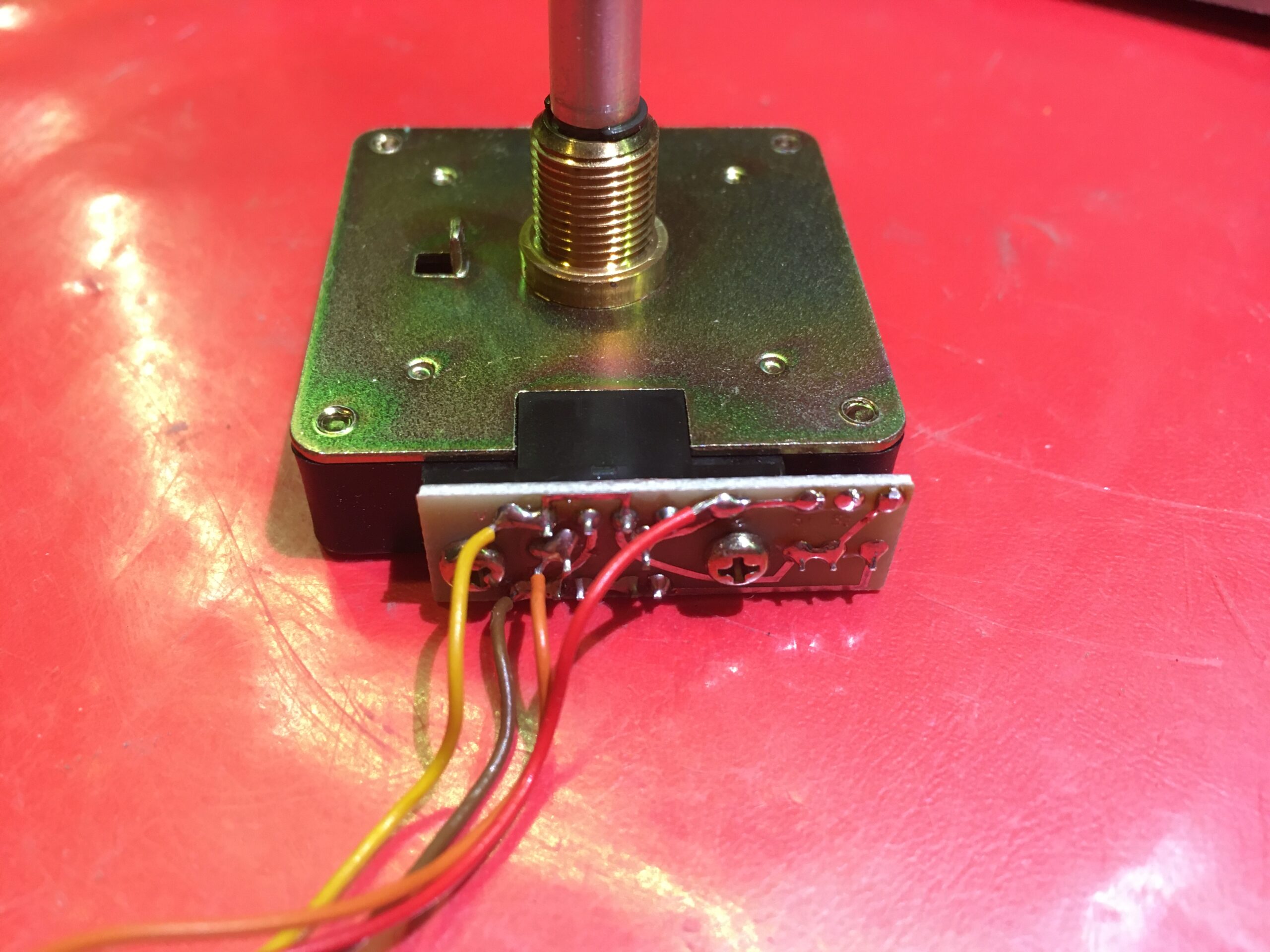
FT-840 Encoder Complete
You should be able to see where the encoder is situated, and the four wires that come from it, leading to a plug that connects to the front of the board on the underside of the transceiver. The colours are: yellow (+5v), brown (0v), red (S1 – output) and orange (S2 – output). You now really need an oscilloscope or logic probe at the very least.
Hopefully you have an old resistor lead that you can poke into the holes on the encoder connector, or possibly a fine probe tip. Connect power and turn on the radio, then check for a pulse train of almost 5v top to bottom, when you check the signal on S1 and S2, whilst turning the encoder shaft. It’s likely one of them will be flat-lined, otherwise we wouldn’t be here! Make a note of which colour the wire is that isn’t producing a signal.
Turn off the radio and proceed to remove the encoder. Carefully disconnect its four way connector on the board. There is a brass threaded sheath on the main encoder shaft, on the front of the radio…it has a flat on either side, so you can remove it with a spanner. Now, carefully remove the encoder from the front panel; it’s a bit fiddly so take your time.
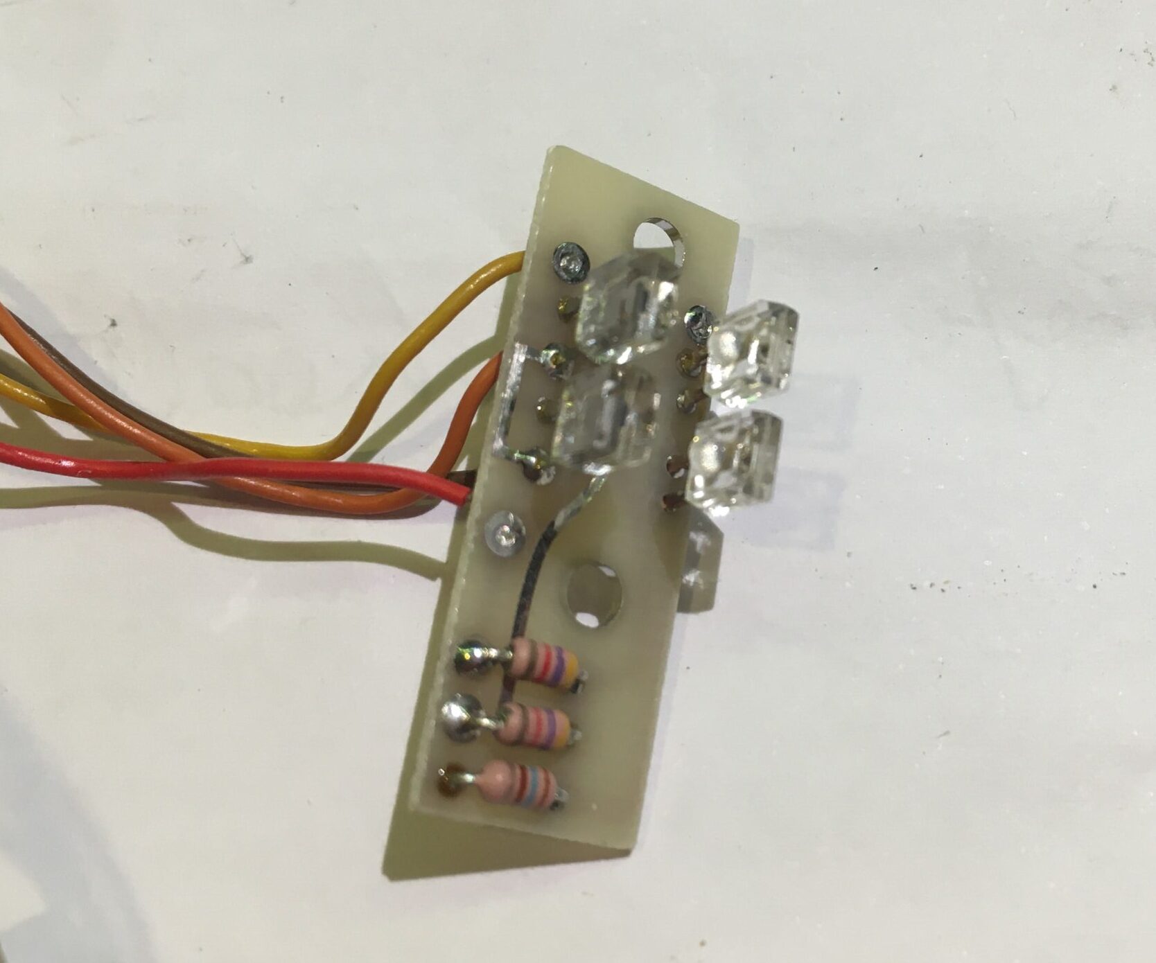
Photo-Interrupter Assembly
You now need to unscrew the two self-tapping screws holding the little PCB onto the encoder. Carefully extract the complete photo-interrupter assembly and put the encoder body away safely so it doesn’t get dust in it. You should now be able to remove the plastic cover from the photo-interrupter, revealing the two emitters and two detectors.
Unless you have a piece of special ‘detector paper’ that glows when exposed to the LED emitter, you can assume that if one of the emitters had failed, you’d get no output on either channel.
The emitters are the two legged beasties and the detectors are the three legged ones.
There is no information anywhere to tell you what the actual parts used are, so I had to investigate. There were plenty of photo transistors and two legged detectors available, but all were far too big and frankly weren’t of the correct functional ‘type’. What these appear to be is an OPIC Light Detector with built in amp and Schmidt trigger. I eventually found two suitable devices made by Sharp, the IS485 and IS486; the difference being whether they give a ‘high’ output under incident light or a ‘low’ output. The IS486 is a match for the functionality in our encoder. They are hard to find and I reluctantly ordered some Sharp OEM devices from China. Note: at the time of writing RS Components in the UK carry the IS485…in theory, if you change both photo detectors, the encoder should work correctly too. But NOT if you only change one.
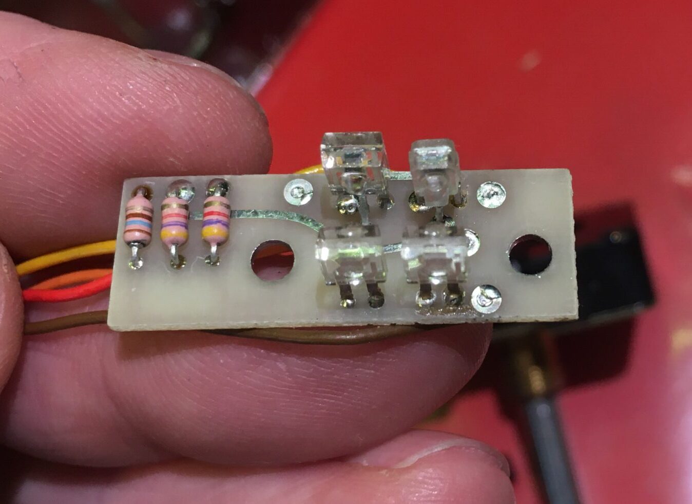
Repaired Photo-Interrupter Assembly
You need to remove the old photo detector carefully, the one connected to the wire colour that gave no output. Then carefully install a new IS486 in its place; the IS486 is slightly smaller than the original part, but is a pin-for-pin replacement…just make sure you align it with the emitter. You can compare it with the remaining original part.
Once you’ve done this, double check your work, then reassemble the encoder and plug it into the FT-840 board and test it before reinstalling it in the radio.
If all is well, reassemble the radio and check it all works. You’ve just saved your radio as these encoders are obsolete and almost impossible to replace, with anything else that fits in the same space.