I’ve built up a small, but growing, collection of W&D boards over the past few years. One of them was a complete transceiver sold to me on eBay for about £10 as a 4m unit…but which turned out to be 70cm. In fact it is a very early crystal controlled transceiver with scanning facilities no less! It works and I intend to re-box it and use it alongside the 2m radio I have. I do indeed have some 4m boards to sort out. Here are a couple of pictures of the radio as found, alongside some words from the designer.
Top Side
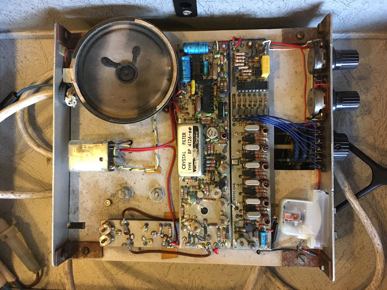 The receiver was a 10.7MHz IF in the early days. Image rejection was poor but then there was nothing there on the image frequency to cause problems. The crystal filter is a 50kHz wide channel spacing that we had specially tooled at Cathodean after we had cleared John Birkett out of all his stock of an SEI equivalent. The crystal line up was (RF-10.7)/5 so will be around 84.5MHz The receiver has a stripline front end with probably a TP393 or BFR91 device.
Mixer is probably a dual gate mosfet such as 3N201 but early ones used a Birkett special. The small board is an outboard pre-amp using similar BFR91/TP393 circuitry which we originally designed to fit in the Starphone handheld. There is a PIN changeover on the front of the main receiver board but with the external pre-amp the changeover is on the other side of the unit with the coax relay. The crystals are manually selected or can be scanned with the on board timer locked to the CA3089 IF chip.
The discriminator is a black ceramic 10.7MHz filter used to slope detect the audio. The black ones were very temperature sensitive and were replaced in later units after being selected for best recovered audio. Squelch operation was a bit woolly. The unused pin near the LM380 was used to shut off the background audio noise when muted. The black coax was RG174 and was awful stuff as it was so easy to melt the inner to outer. I can’t see the feed from the multi-channel board into the receiver oscillator but this could be underneath.
Underside
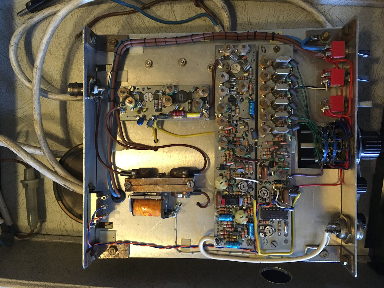 The transmitter boards has an mic amp which feeds across on the white wire into the multichannel oscillator board which from memory had a phase modulator. I think the IC on the multichannel board is a tone burst. The transmit strip is a x36 on the crystal (x4x3x3) and the output power is 500mW from the SRF1117 (another Birkett special). The device was not very reliable and the ceramic lids used to come off. We used BLX67s and then SD1080.7 as a replacements. The PA board takes the 500mW output to 3W in the BLX67 pre driver (also used SD1135)and then 10W from the final which could be a 2N5946 or maybe a SD1136.
It is very early first generation and I had forgotten we did this version. If was very popular in the early Phase II UHF repeater era (1978/1979) where there was nothing on the market to meet demand. The repeaters were all on 50Khz spacing. We went public with sales at the Woburn Rally in 1978 and picked up probably half a dozen brave souls who bought the receiver and transmitter as single channel only units and the multichannel and PA followed the following year. Some sales went to Norfolk and the club there bought a bulk batch for their repeater group as did Andover and Reading. Things then started to pick up.
Many of the components came from John Birkett of Lincoln and he became an outlet for the kits at the Rally events when we did not attend ourselves. He had one of the dealer display cases (more on that later). The receiver changed a lot as it evolved, the transmitter very little and the PA hardly at all apart from different devices depending on availability.
Remember that these radios came out when G8s could only operate on VHF and above. The 2m and 70cm bands started to become much busier as radio amateurs modified old PMR equipment and built their own gear. Happy days for many of us.