VK5JST Analyser by M5POO
For some time now I’ve hankered after an aerial (antenna) analyser. Almost everyone I know has an MFJ of some kind…most have been well used too. Rather than keep borrowing one or another, I decided having my own was a good idea…but there are quality issues reported with some MFJ units, and they use surface mount parts which can be difficult to replace. Having searched the internet I came across the VK5JST Aerial Analyser…and ordered one from Australia at the Adelaide Hills Amateur Radio Society website. Update 2020: AHARS no longer supply the kit and Jim now supplies the kits for a new analyser, which includes 50 MHz, directly. His website is here. You can pay using PayPal which makes ordering a breeze.
The project was designed by Jim Tregellas and was published in 2005. Since then, around 17,000 of these analysers have been built; around half from the kit and the rest scratch built. I was drawn to it as a) it gets rave reviews, b) it covers HF only which is all I need and c) I could build it myself…and repair it should the need arise. There’s a mass of information on Jim’s website which is here, and even the code for the PIC chip is there for you to modify if you wish.
Before I go any further, you need to understand that VK5JST’s aerial analyser kit is supplied at minimal cost…so that amateurs in poorer countries can afford to buy it. The kits are packed and sent by volunteers, with any profits going to the Adelaide Hills Amateur Radio Society.
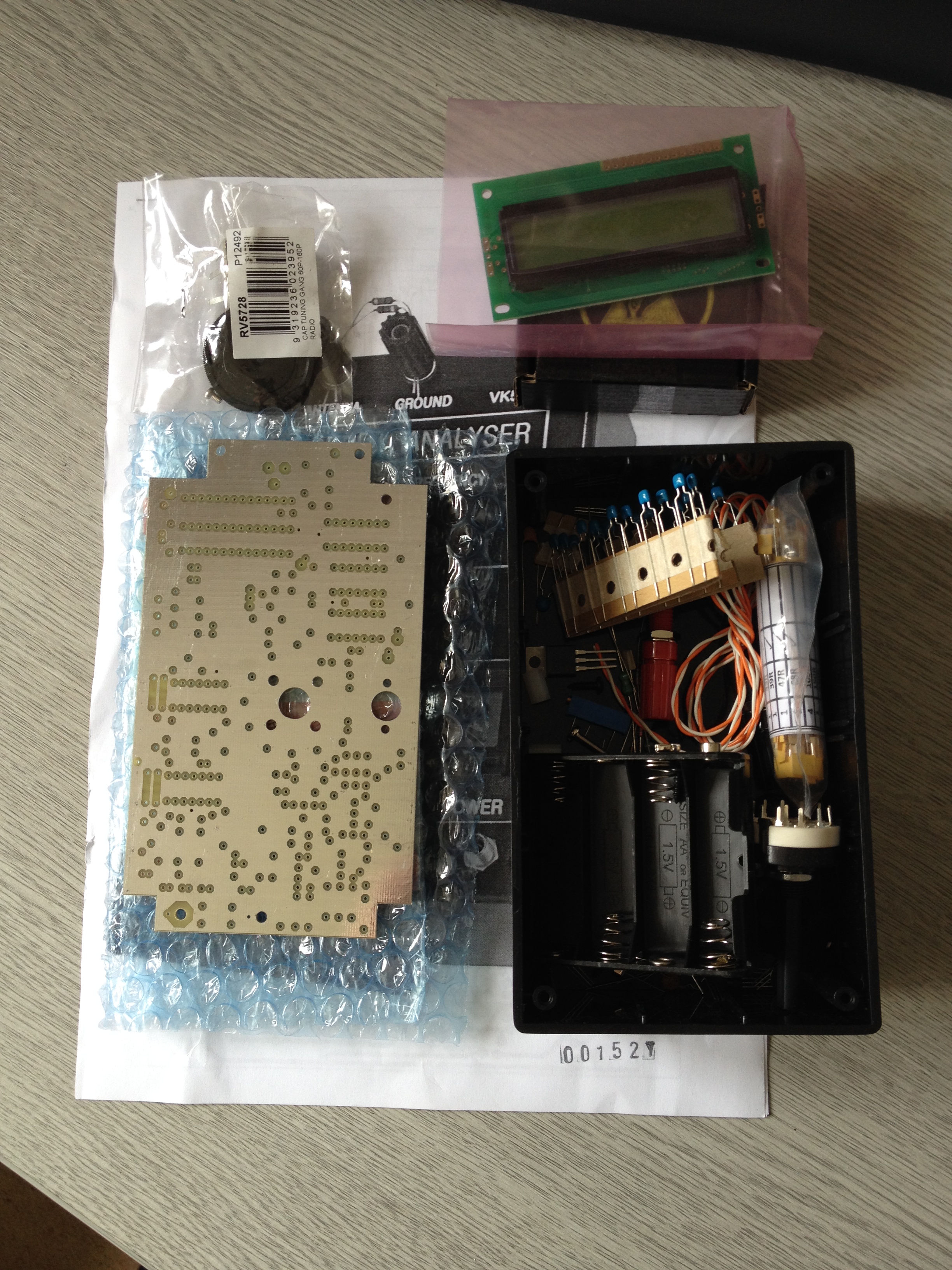
VK5JST on arrival
The kit cost me around £80 including postage, with no ‘duty hit’ from the UK Post Office…it arrived remarkably fast too. On opening the kit, all the components were rattling around loose in the plastic box…slightly concerning as some of the IC legs were bent. They were easily straightened however and the PIC chip had been wrapped in foil to protect it.
The ready made front panel was wrapped in bubble wrap and the display in an anti-static bag. The first step was to organise the components for assembly after reading the supplied instructions and Jim’s website.
Some construction hints and experiences
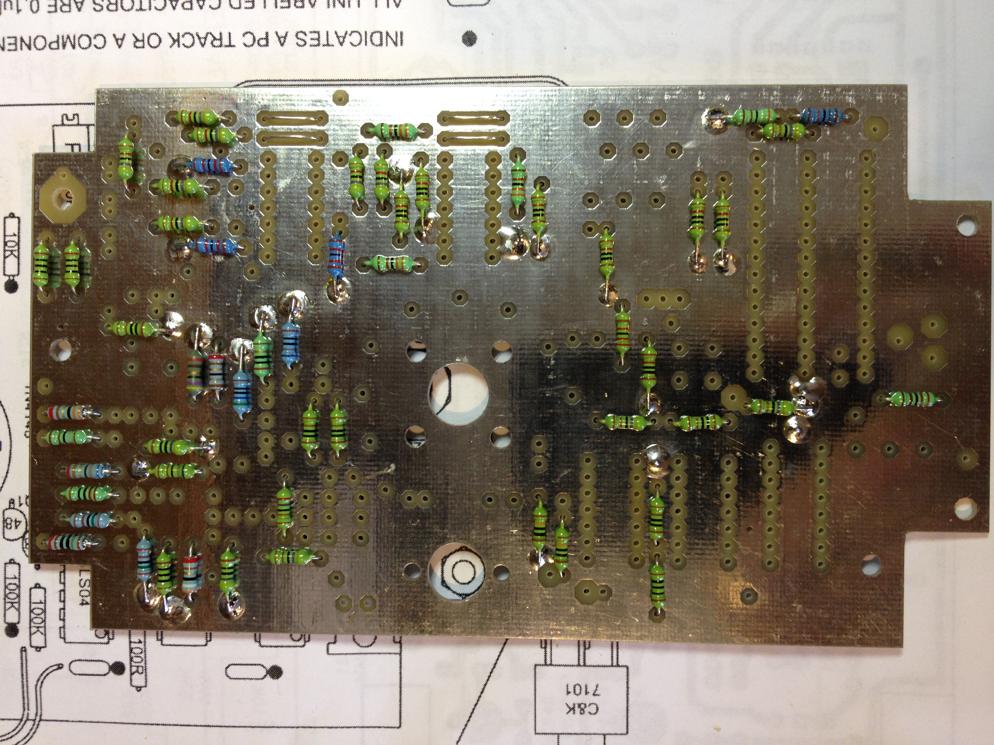
VK5JST Assembly Stage 1
Make sure you use the PCB as a template for marking holes on the lid of the box…before you start fitting components.
To save on cost, the PCB has no silk screen component layout printed on it, so install resistors as ‘landmarks’ on the board to help. Note that any component connected to ground, is in fact soldered to the ground plane, i.e. the top of the board; there is no hole for the lead. Remember to fit the through board links and then the lowest profile parts first; it will make your life easier. The usual ‘take your time and check everything twice’ advice is essential when building this kit; I checked every resistor with my Fluke meter before installing them.
VK5JST Assembly Stage 2
There are seven germanium point contact diodes used in the detector circuits…those in your kit should all be the same but you may not know which of the variants you have been sent. It is essential that all the diodes are the same type, and better still that they are all matched for forward resistance.
Unfortunately one of mine broke the moment I tried to bend the leads to fit the PCB. The first replacement later turned out to be a failure, but another one was OK…more later. I’ve posted the pictures of my assembly stages as they might help you when you build yours…but read the documentation and website.
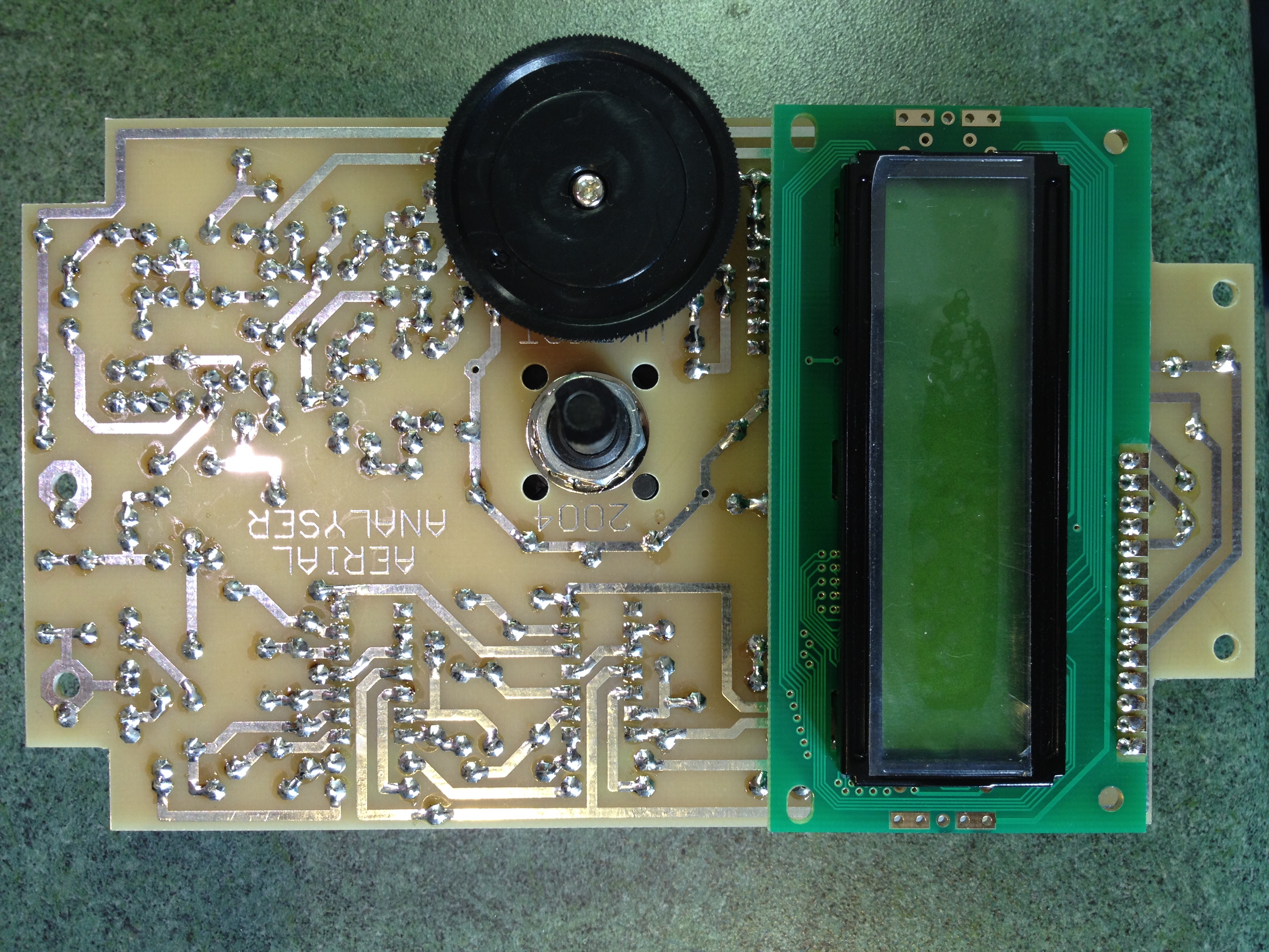
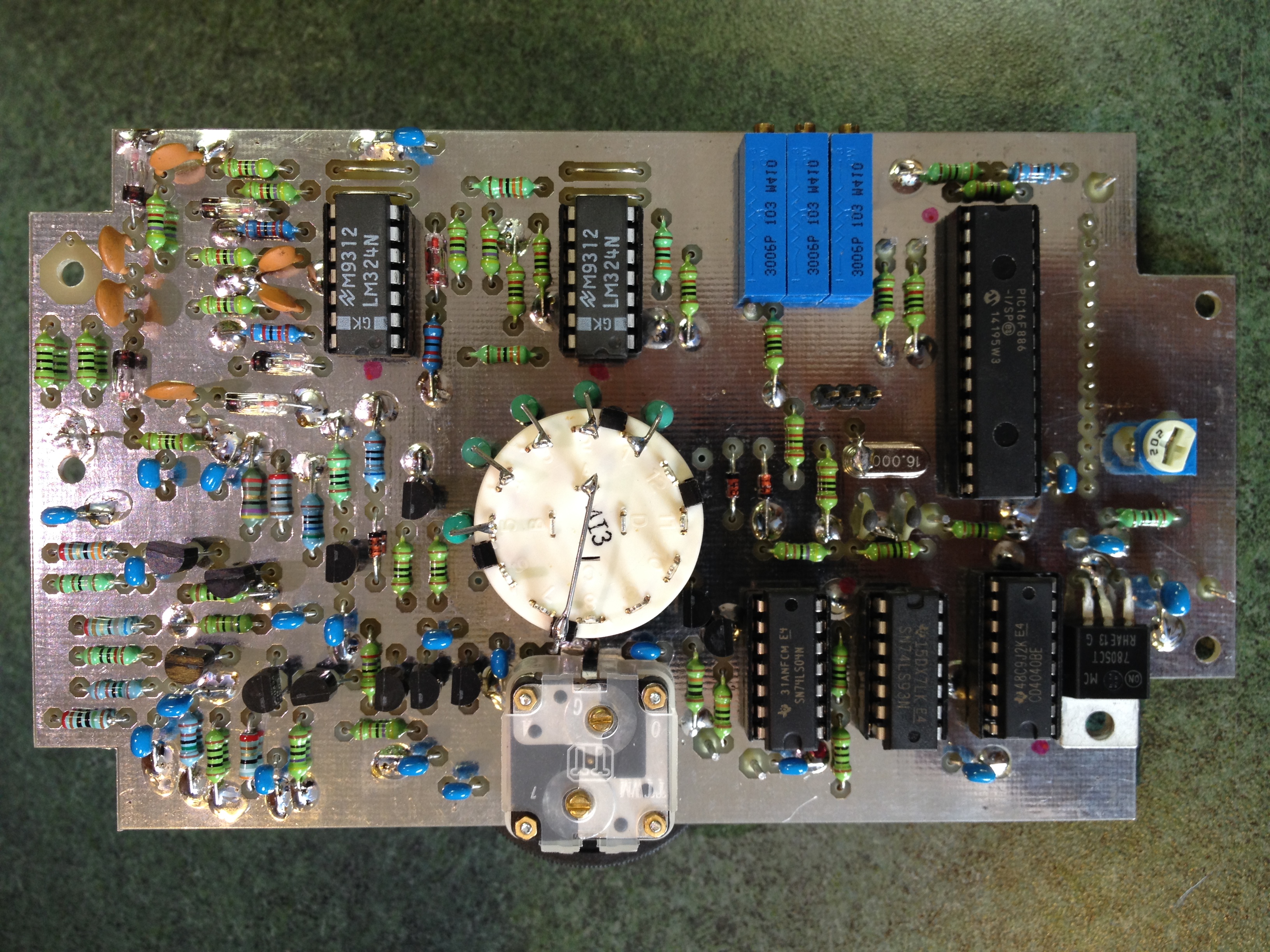
VK5JST Assembly Stage 3
When mounting the display, it sits about 6mm above the main board. I used a turned pin header socket strip soldered to the display PCB, and some of the trimmed resistor leads, to make a connector which could be removed. Push the resistor lead trimmings in to the header sockets firmly, then insert the assembly in to the main PCB, solder and trim the leads. I actually had to make mine a bit long initially so I could get the soldering iron in…then I clipped the wire ends back about 3mm each.
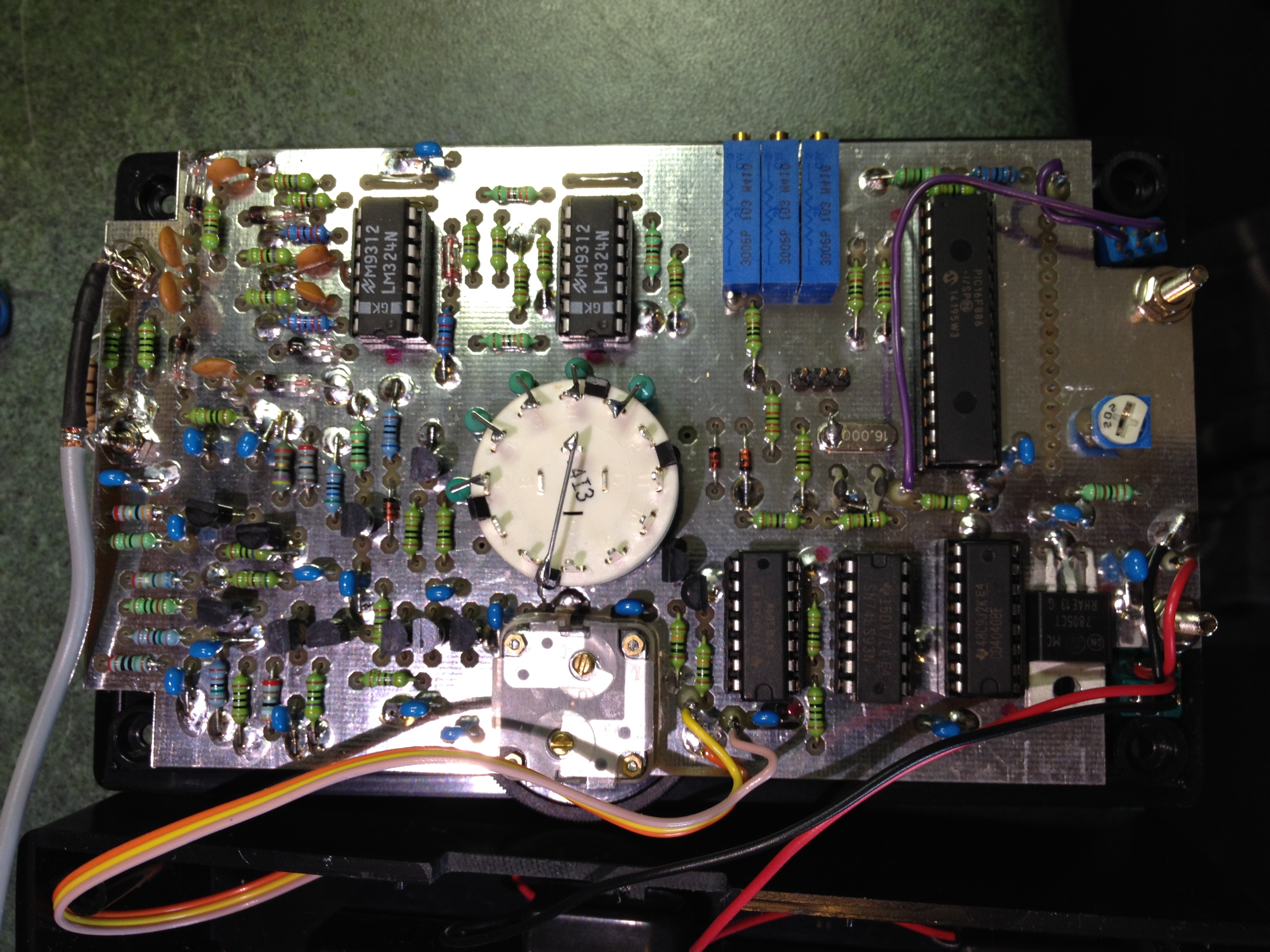
Once you’ve installed all the components…leaving the IC’s out for now, double check everything you’ve done, then connect a 12 volt supply; regulated to about 200mA if you can. Ensure the 5 volt regulator is doing its job, the follow Jim’s instructions for getting the VK5JST Aerial Analyser up and running. I did add a BNC socket to the back of my analyser as most of what I check is 50 ohm coax fed.
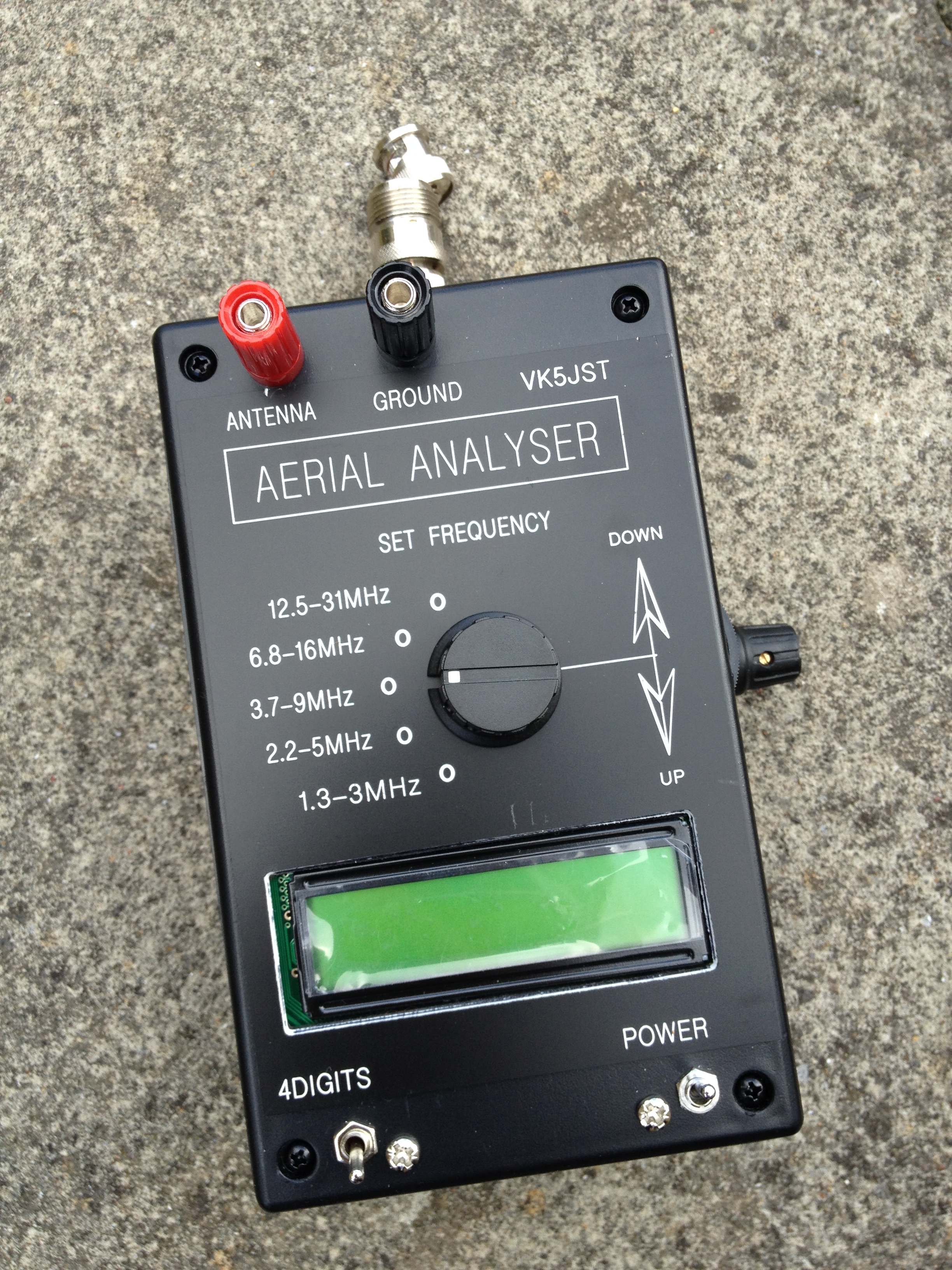
VK5JST Built
Note: the two little toggle switches supplied with my kit were frankly weak and nasty…any attempt to tighten them and they broke apart. I suggest you throw them away and find some better ones.
Frankly, the hardest part of building the kit was making the rectangular hole in the box lid for the display, and filing the slot for the coarse frequency knob. Black plastic powder and swarf was everywhere, and it becomes statically charged too…so you have to chase it around the box with your finger to remove it. My advice is to wash and dry the box and lid when you’re finished. The final jobs are to assemble the gubbins into the box 😉 You may have to clip out pieces of the PCB guides in the box as the PCB is just a little big to fit easily.
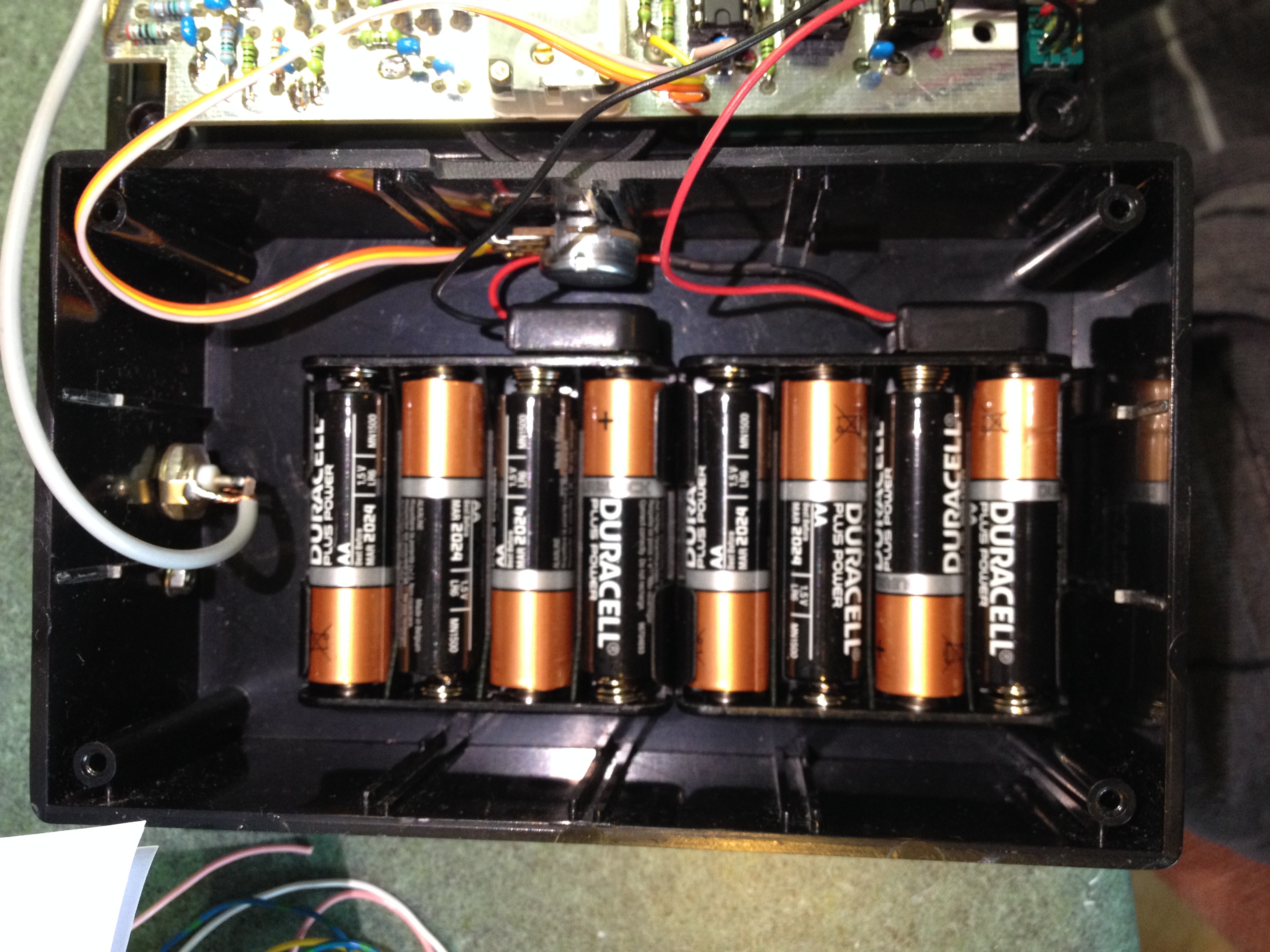
VK5JST Batteries
Use double sided sticky tabs to hold the battery boxes on the bottom, and find yourself four small rubber feet…job done.
I did have some contact with Jim, thanks to the dodgy diode, and he provided some additional advice regarding calibration. He recommends that instead of the 4.5v and two lots of 2.25v suggested in the instructions, you should use 4.4v and two lots of 2.14v.
During calibration, I found my analyser read slightly out using the 270 ohm resistor. This is still within the tolerance of the analyser and as Jim says, I’m unlikely to be setting an aerial up for an SWR of 5 anyway 🙂
Notes from my build
- Make sure you keep the detector components a little off the board as suggested in the instructions.
- If you can, ensure all 7 of your germanium point contact diodes are fairly closely matched for forward voltage drop…Jim suggests Russian D9B diodes if yours are out. The AHARS kit supplier does not provide spare parts.
- Replace the nasty toggle switches with decent ones.
- The VK5JST Aerial Analyser draws very little current but you should still use decent alkaline batteries to supply it.
- Before you start adjusting the ten turn pots for calibration, let the analyser settle for 20 to 30 seconds. The readings do change a tiny bit after switch on, presumably due to either the battery voltage reducing a fraction or a small amount of heating in the detector diodes.
The acid test
To check my analyser out, I visited a radio friend with an older but trusted MFJ analyser. We compared the two units on a variety of aerials and on all bands. My VK5JST Aerial Analyser gave a really good account of itself. The slight error was there at high SWR but it did the job admirably. I found one of my diodes was about 10% lower in forward resistance to the others, which is probably the cause of the error. I’ve no plans to fix it right now as it really isn’t an issue…but I might in the future.
Modifications
If you look around the internet you will find great reviews such as eHam here. You will also find several sites with mods and suggested improvements. If you want to play around or ‘improve’ the design, so be it…but I can assure you that if you build your kit carefully it will work and ‘do what it says on the tin’. Don’t try and reinvent the wheel, so to speak. Jim’s design has been going for ten years now and 17,000 have been built…surely that should tell you how good it is.
One thing I might add to mine is an audible tone which rises and falls with SWR…it will make aerial tuning a little easier out of doors.
Enjoy building and using your VK5JST Aerial Analyser 🙂