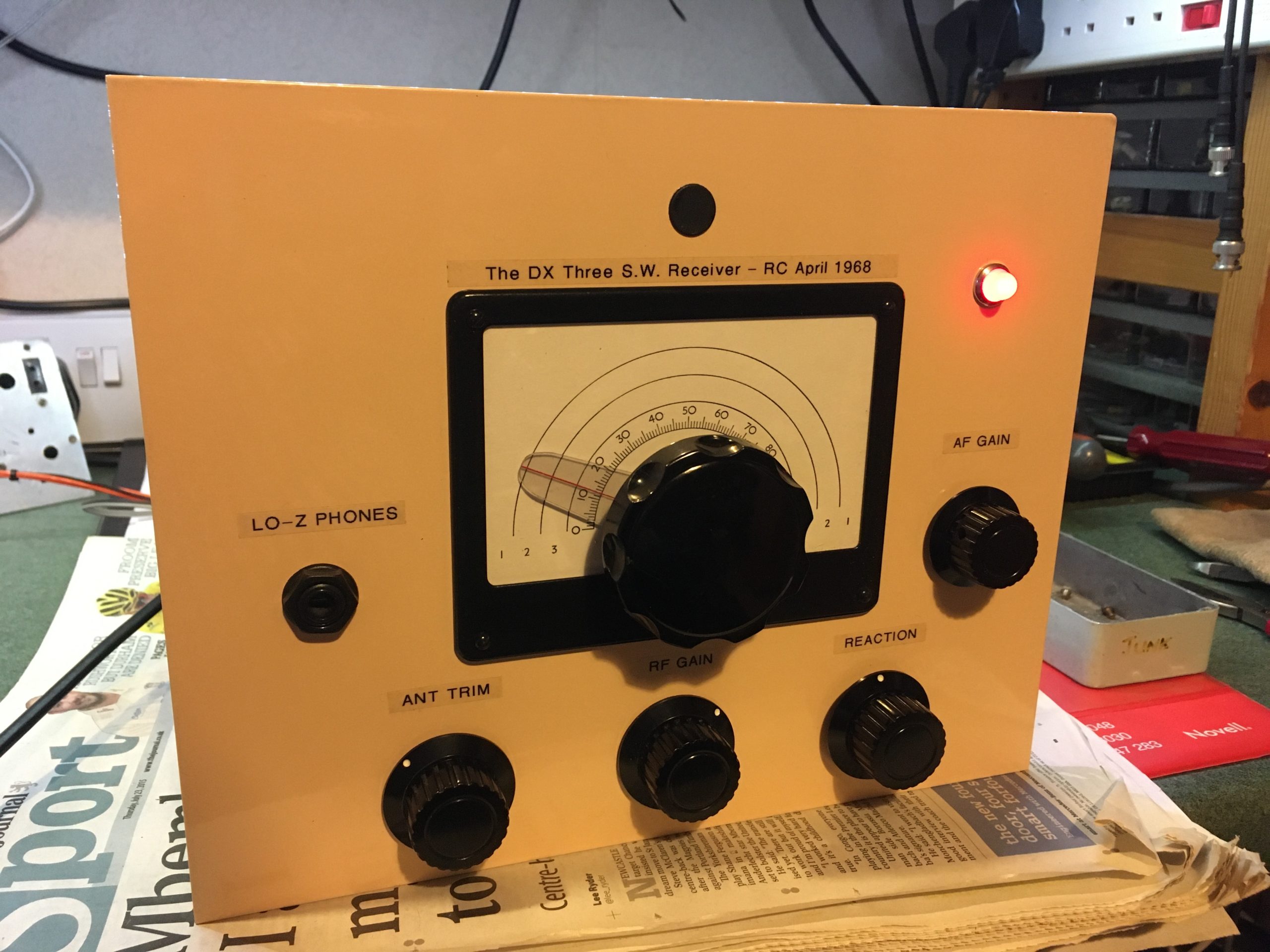
Front Panel
Back in the 1920s and 1930s, most wireless sets (radio receivers) were of the TRF (Tuned Radio Frequency), Regenerative or Crystal Set type. It depended on how much money you had and your constructional skills. These were very simple radios and most were perfectly satisfactory for local station reception; back then, high fidelity was impossible with the technology they had. Components and parts were quite large and the valves used to make the radios were expensive.
Edwin Armstrong’s superheterodyne receivers were very much for the wealthy households, and beyond the skill of many constructors.
Many people, myself included, get a great deal of pleasure building and using simple receivers from bygone days. Fortunately we have the benefit of much more up to date components, from the 50s, 60s and 70s. Some are still made today of course, and hi-fi enthusiasts often prefer the sound of old, valve technology amplifiers.
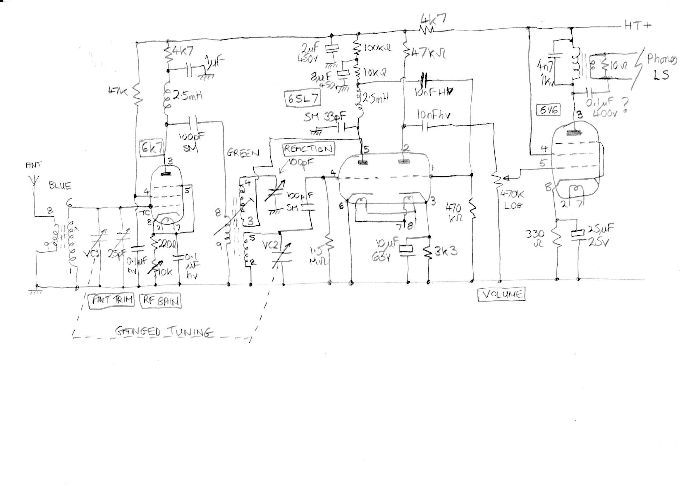
Circuit Diagram
The receiver featured here is a regenerative type, with an RF amplifier stage (1), a detector (V) and two audio amplifier stages (2). The old designation is therefore 1V2. One of the major problems with regenerative receivers is that they can radiate their oscillator if they are incorrectly adjusted; the interference is on the signal frequency so causes other local listeners problems. They were known as ‘oscillators’ or ‘howlers’. The use of an RF stage ahead of the detector, greatly reduces this effect, as to receive SSB and CW signals, the set needs to be adjusted so it just oscillates. To receive AM and broadcast stations, it needs to be adjusted to just below the point of oscillation, and that’s where the old timers got it wrong; many older people can’t hear high pitched whistles and squeals from an oscillating receiver.
My receiver came from a fellow radio amateur who knows I like playing around with these basic designs. It looked very tidy on top, but appeared unfinished and a bit of a ‘birds nest’ under the chassis. It uses Denco green and blue coils and has storage for coils not in use. I worked out which connections were for the heaters, HT, aerial, earth and loudspeaker. Once connected, I brought it up slowly on a variac. The noise was terrible, with a loud rasping hum accompanied by whistles and squeals when the controls were turned. I did briefly manage to hear Radio 5 Live from Stagshaw up the road, but then anyone with an old style filling in their teeth can hear that…without a radio.
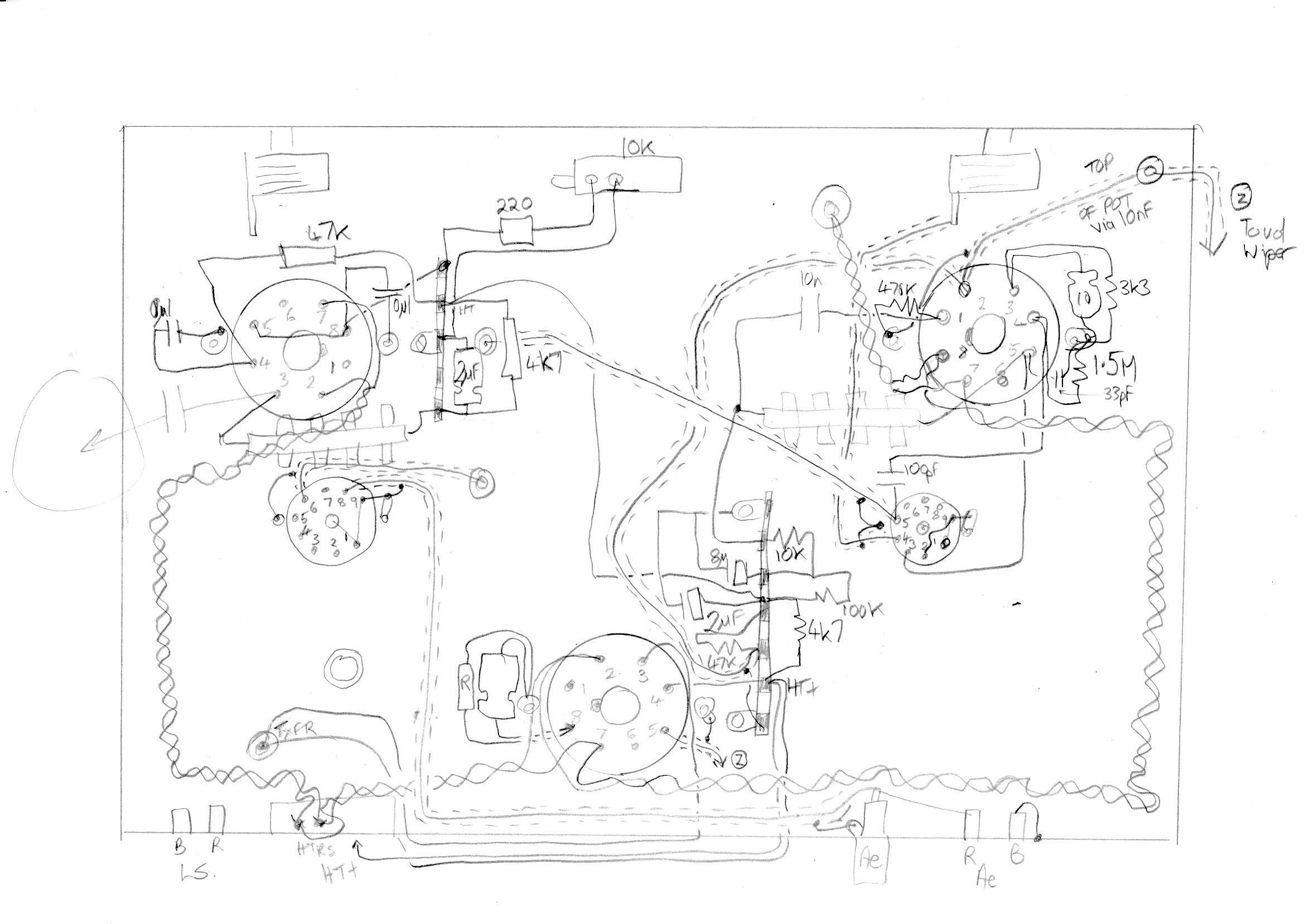
Under chassis layout
There really was little option but to draw out and correct the circuit, then strip the receiver down before rebuilding it. During the rebuild I carefully planned the layout to minimise components wire lengths, interconnecting wire lengths and to use screened cable where necessary. It was time consuming but revealed a very familiar design, the detector of which is Edwin Armstrong’s regenerative circuit, which he designed in 1912 and patented in 1914.
The RF amplifier stage in my receiver is a 6K7 variable mu pentode which then feeds a 6SL7 twin triode, the first section is a detector and the second is the first audio amplifier. Finally, a 6V6 beam power tetrode drives a loudspeaker to a good volume. Tuning is via a two gang variable capacitor of around 365pF per section (mine is actually around 300pF per section) and regeneration or ‘reaction’ is controlled by a 100pF variable capacitor. Blue Denco coils are used in the RF stage and green Denco coils in the regenerative detector.
Note that there is plenty of supply decoupling used in the receiver and I run it from a small variable power supply, which is exceptionally stable and noise free. I did manage to track the dual gang variable capacitor quite well, but found the aerial trimmer variable capacitor at 25pF, provided the signal peaking I needed.
After rebuilding the little receiver performed really well, tuning and reaction were smooth and predictable. A great project and well worth the effort. You should try one too.
Here’s a photo gallery showing the underside and top of the chassis during rebuilding. Hover over the image to stop the slider, or use the arrows and thumbnails.


