I recently bought an original Yaesu FT101 in an ‘as seen’ condition. There was no accessory socket blanking plug or mains connector supplied with it.
WARNING: this information is provided on an ‘as-is’ basis. You undertake the wiring of this socket of your own volition on the understanding that you are competent to do so and can check your own work. This post refers to the original FT101, and may not be correct for later models.
FT101 Mains Connector Wiring
It seems that the original wiring diagram doesn’t respond to a Google interrogation, so I borrowed a working lead from a friend, before making up my own.
On the rear of the original FT101 the power connector is actually comprised of the male part, which has flat pins sticking out from the back panel, and the part that goes on the end of the mains supply cable, the socket…it has slots for the male bits to fit into!
The connectors are actually the same as the wartime and onward ‘Jones Connectors’, much loved by radio and electronics people. There is a difference though I believe…the pin numbering is not the same, the left and right side numbering being transposed for some reason.
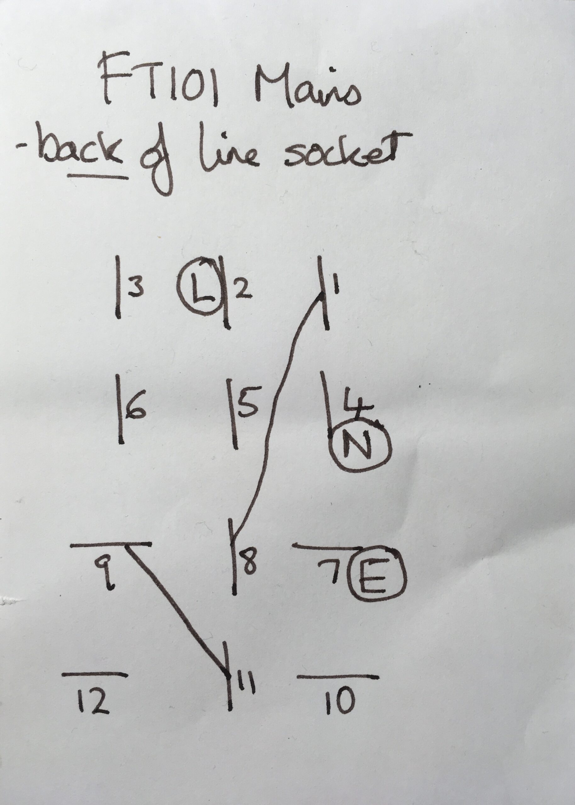
To avoid confusion, here’s how the diagram works. If you plug your female connector without its outer shell, into the back of the radio, then view it from the back, you will have a view similar to the one in the diagram. Ignore the numbers unless you have a genuine Yaesu connector, and just follow the pattern. There are two links to make and the L, N and E connections are shown.