These are truly excellent radios; well made, reliable and a pleasure to use. In the UK they are marketed by Kenwood, but in other countries they carry the TRIO brand. The TS-770 covers 144 to 146MHz and 430 to 440MHz with around 10w output from SSB, FM and CW modes. They DO NOT have a CTCSS board as standard, but there are several aftermarket options available if you need that functionality. The FUNCTION switch allows you to work split frequencies, or in fact, cross band. There are separate aerial sockets (N-type) for each band.
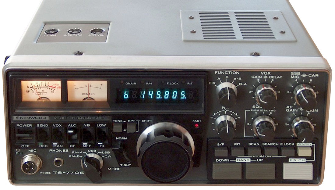
TS-770 Stock Photo
This particular radio came my way quite recently at a local radio rally. Apparently the VFO knob turned, but the frequency didn’t change; a very common and easily resolved problem in most cases.
Apologies for the lack of photos, but I’d already boxed up the radio before deciding to write this post.
Resources:
The full specification of the TS-770 is at RigPix, where you will also find a link to the Service Manual.
There is a poor copy of the User Manual here.
There is a really nice copy here.
Here are the problems I found:
All three dial lights were out
15 ohm 1 watt resistor
This happens to virtually all transceivers that use ‘old’ incandescent bulbs. The TS-770 uses small, wire ended 12v bulbs; three of them in parallel to be precise. They are fed from a 14v rail through a 10 ohm 1w resistor. The resistor needs to drop 2v so carries 200mA.
The old bulbs are very similar to the old VHS video recorder ‘cassette lamps’ that provided we ex-video repair people with a regular income back in the 1980s. I have some, but as with most components, can’t remember which ‘safe place’ I put them in. So, I used three 12v pea bulbs with wire ends, carefully soldering some thin wire to them so that the leads would reach the supply tags. The bulbs were too small to be held in the rubber bulb mounts, so I had to resort to a small blob of Blu-Tak to hold them.
If you do this, don’t just reconnect the bulbs to the 10 ohm resistor, as bulbs don’t all draw the same current. I measured the current through my bulbs and felt that a voltage reduction to 10v would be bright enough and add longevity to the life of the new bulbs. After the necessary computation, a 15 ohm 1w resistor was duly fitted and full illumination restored.
VFO frequency not changing when knob spun
This problem will affect ALL of these transceivers at some point, probably more than once. There are two presets on the VFO knob PCB, VR2 and VR3. Page 74 of the TS-700 Service Manual explains how to set these with the aid of an oscilloscope…it actually suggests driving the VFO knob with a motor, but I managed by turning it with my hand.
The problem is normally due to a noisy preset track, so simply ‘exercising’ the rotating part will normally do the trick. A dab of contact cleaner may be required in difficult cases.
Once you get the mark-space ratio correct, check the phase relationship of the two pulse trains and you should be good to go.
Low output at bottom of 70cm band 430 to 432MHz
Someone had been ‘playing’ inside the radio for some unknown reason, I suspect their intention was originally to replace the dial lights. There appeared to be no signs of bodging and the bandpass filters on the RF Unit PCB were still as set by the factory. There is a MIX(B) unit mounted behind the panel meters, which had tempting threaded shafts sticking out. It turned out that one of these had been slightly misadjusted, and once corrected, full output was present across the 70cm band.
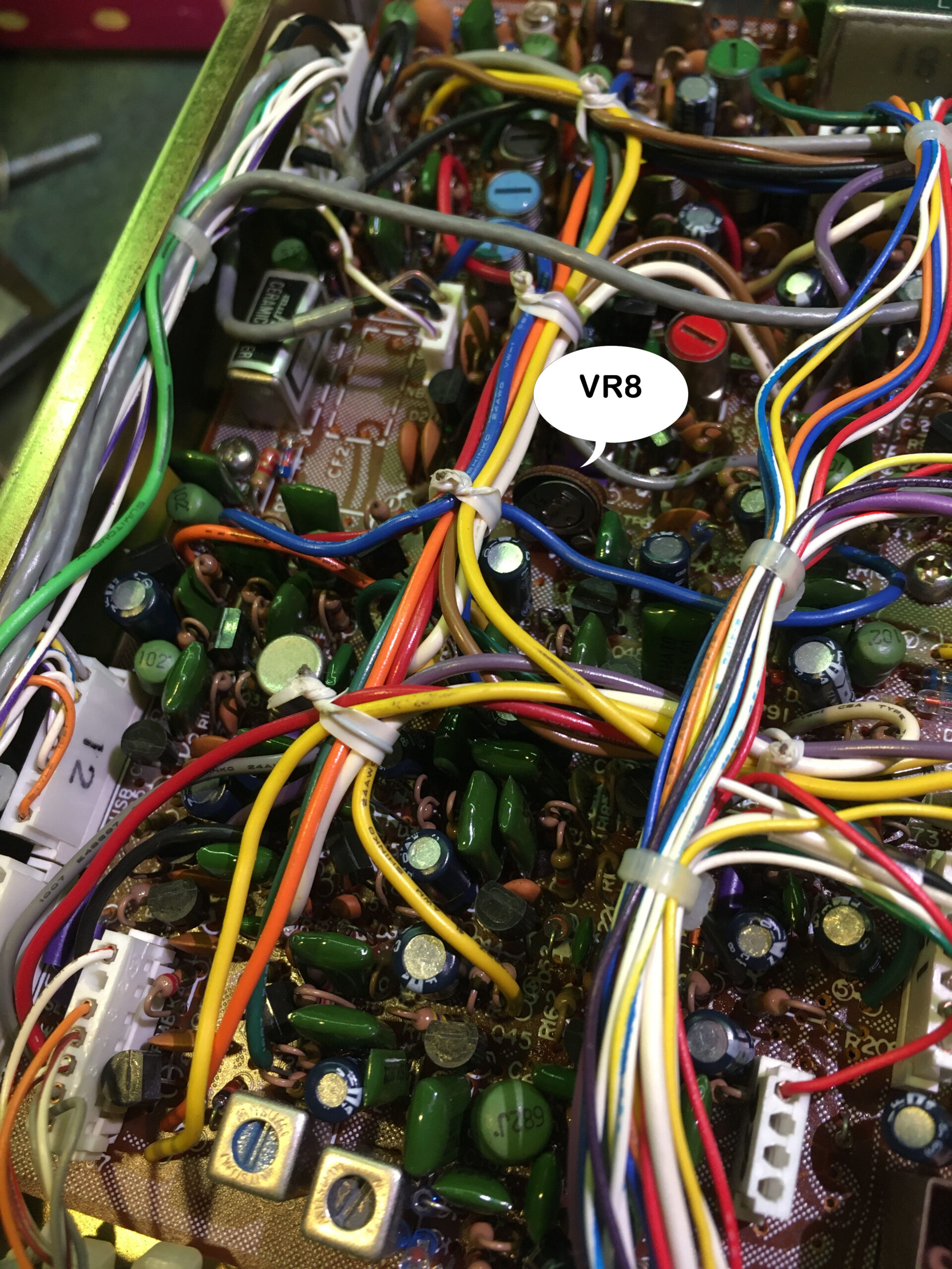
Location of VR8 on IF Unit
S Meter almost no reading on FM
I didn’t notice this until all the covers were back on…doh!
What could it be? A quick check of the circuit revealed that VR8 on the IF UNIT was responsible for the meter sensitivity. Again, the track was a bit noisy and a quick clean and exercise restored normal operation. The wiper had been set fully clockwise and it turned out that this was the best setting for the meter.
Noisy switches
Essentially, the MODE and FUNCTION switches were a bit noisy. The application of a little contact cleaner through a fine nozzle and a little exercising of the switches restored normal operation. Make sure you use a good contact cleaner…I used one without a lubricant as there was none on the switches originally.
Slow/Fast button not working
I’m used to dealing with old style TTL and CMOS logic, so this was thankfully another fairly straightforward repair.
The ‘S/F’ button increases the tuning rate ten fold when pressed, and turns the ‘FAST’ LED on; press it again, and you’re back to slow. When pressed, the LED flashed momentarily but stayed off, and the tuning rate didn’t change. Not the end of the world, but a pain if you’re band scanning or moving from one end of a band segment to the other.
The ‘S/F’ button grounds the ‘SF’ control line that feeds into the DIGITAL UNIT (DU), which is conveniently (not) located under the RF UNIT…which has to be removed completely to access the DU.
One course the SF line follows, is through C7 and on to pin 3 of IC 7; that was working normally.
The other course it follows is to a flip flop made up of IC 5, sections ‘b’ and ‘c’ according to the diagram. There are three naughty little tantalum capacitors around that circuit. A quick check revealed an almost negligible change in voltage across C4, a 1uF 50v beastie. Removing the DU looked a little daunting, but instead I carefully removed the capacitor from the top of the board, and found it measured around 700 ohms when it should be effectively infinity after initially charging. A suitable replacement was procured from the bowels of my capacitor store and fitted, again from the top of the board; it is through hole plated you know.
This restored full operation. I’m guessing that if the VFO was stuck in FAST tuning mode, C5, another 1uF 50v beastie, would be the culprit.
If you like operating on 2m and 70cm, you could do far worse than buying a nice Kenwood TS-770…if you can find one!